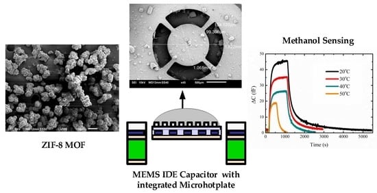
A Low-Power MEMS IDE Capacitor with Integrated Microhotplate: Application as Methanol Sensor using a Metal-Organic Framework Coating as Affinity Layer

 , , , and
Abstract
:
1. Introduction
2. Experimental
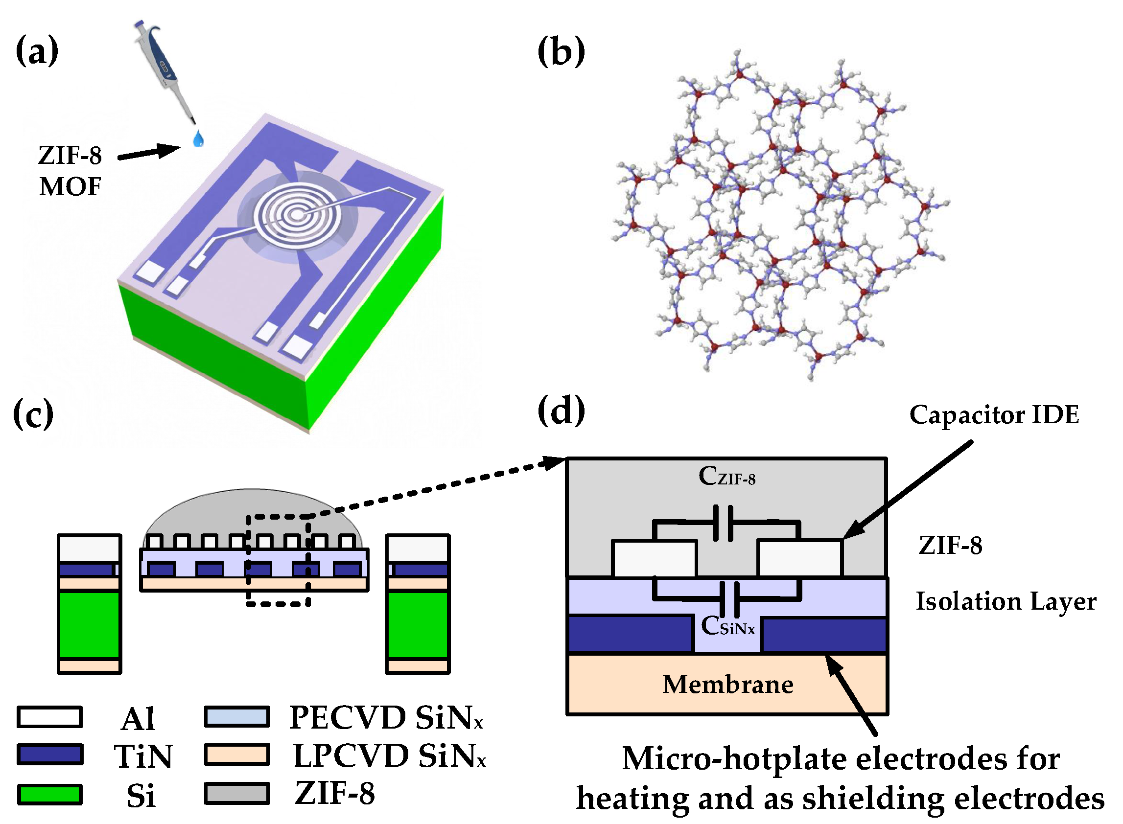
2.1. Device Design
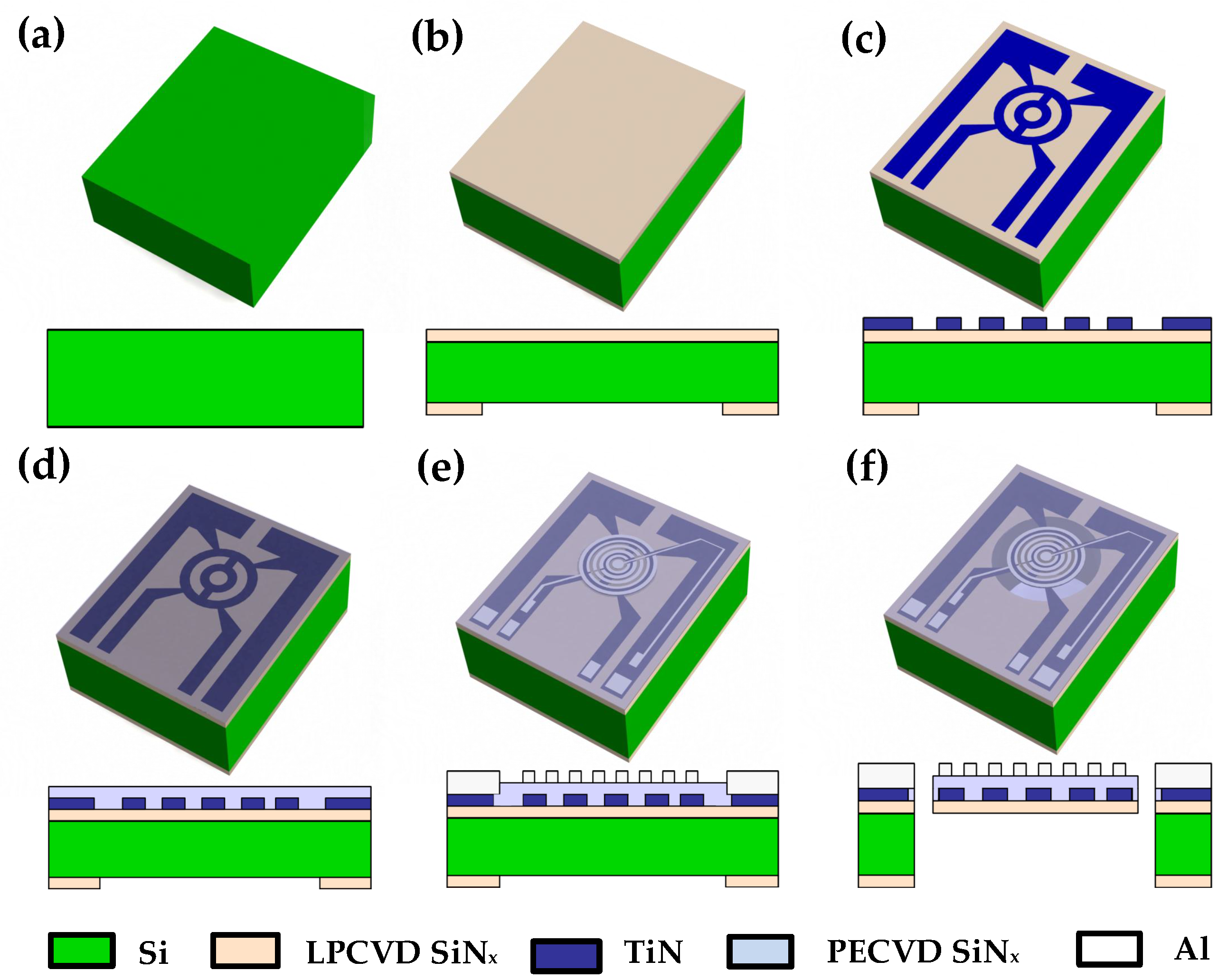
2.2. Device Fabrication
2.3. Synthesis of ZIF-8 MOF
2.4. Structural Characterization
2.5. Experimental Setup and Measurement Procedure
3. Results and Discussion
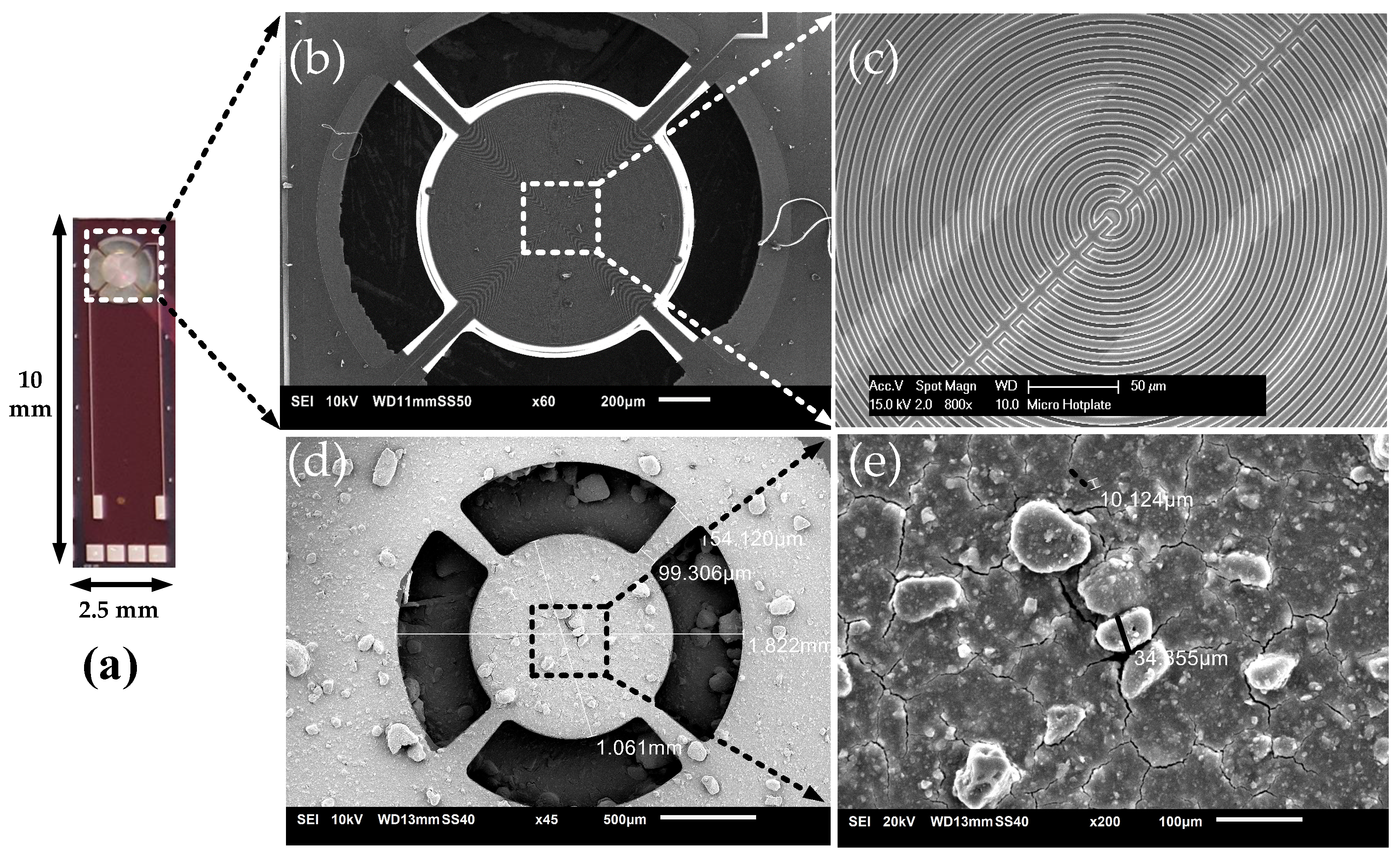
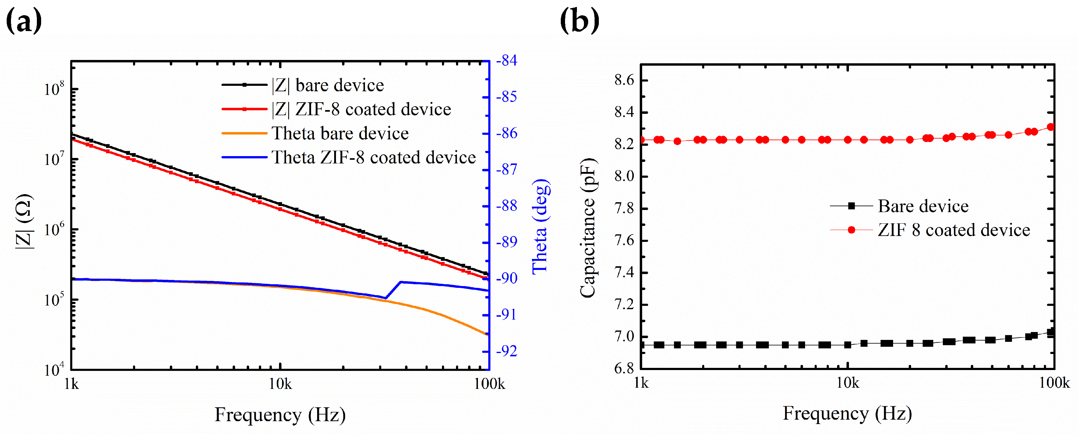
3.1. Device and Material Characterization
3.2. Thermal Characterization
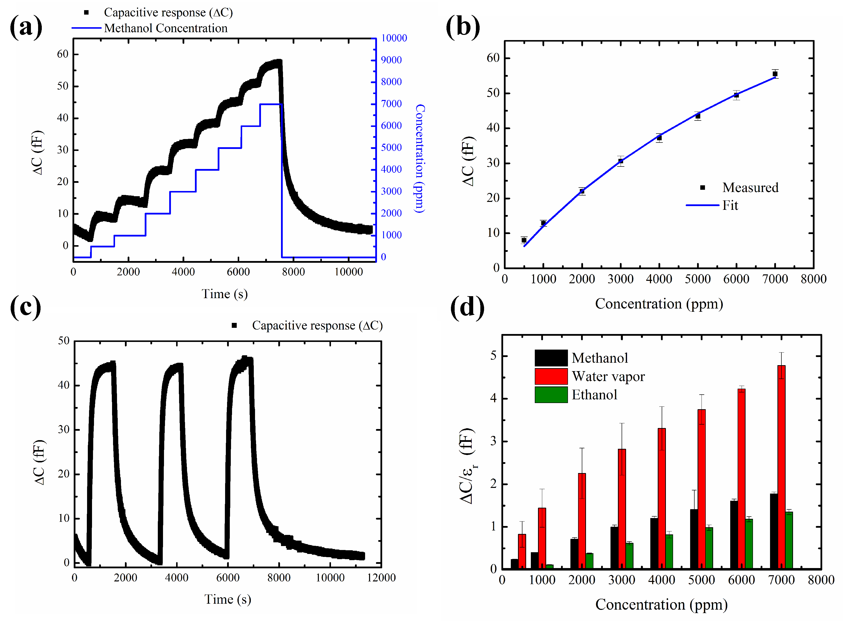
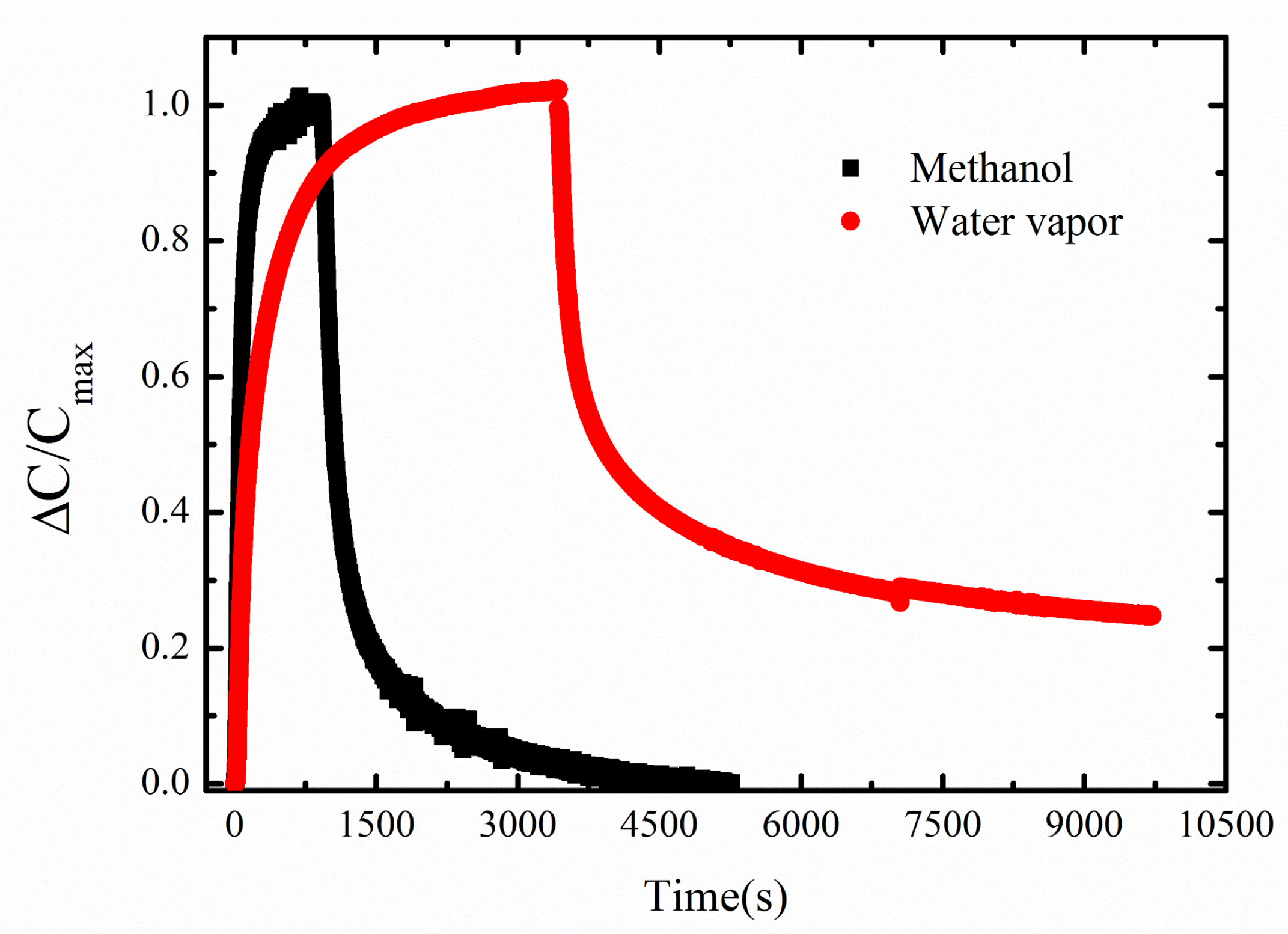
3.3. Sensing Measurements
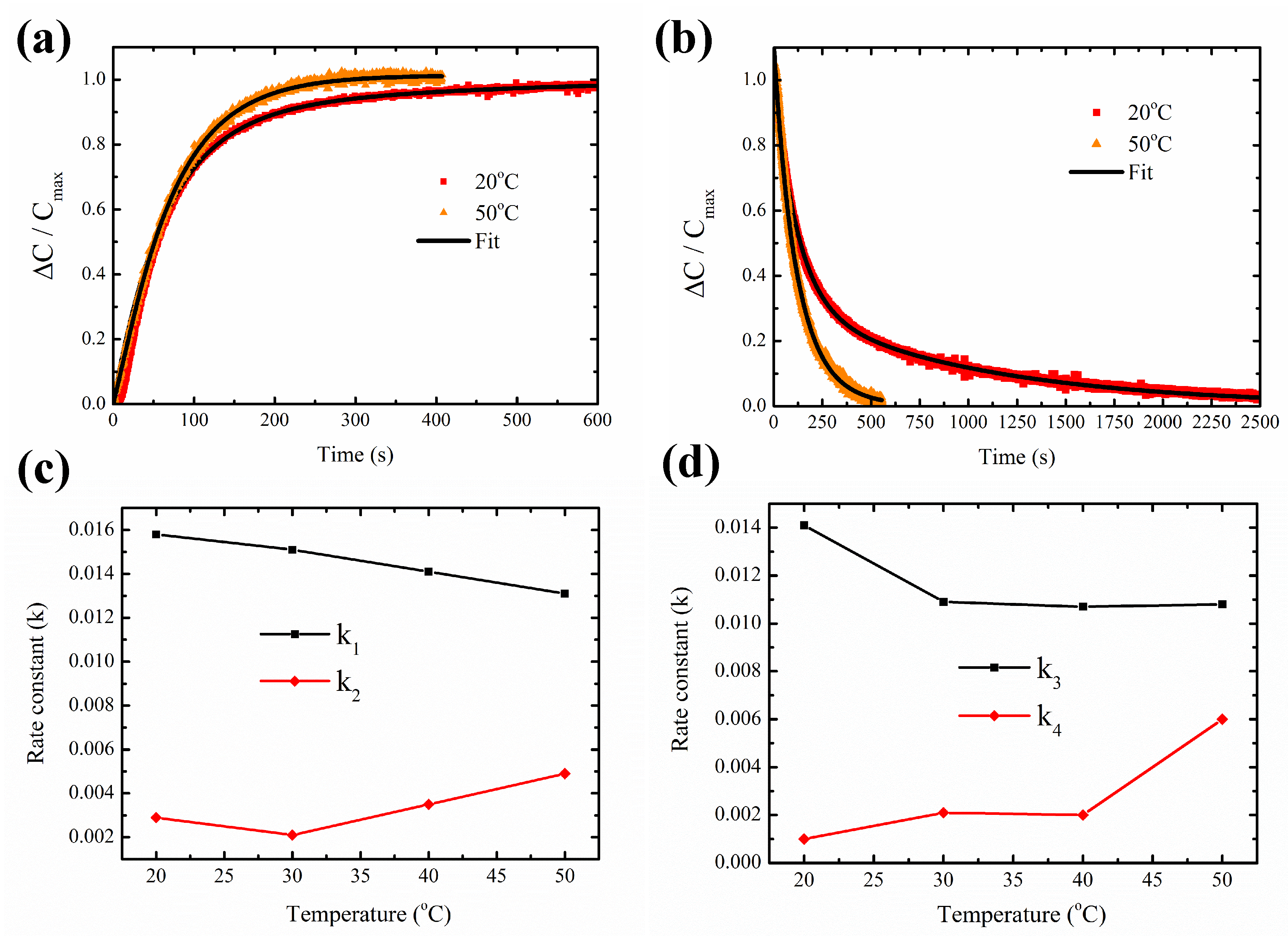
3.4. Temperature-Dependent Adsorption and Desorption Kinetics
4. Conclusions
Supplementary Materials
Author Contributions
Funding
Acknowledgments
Conflicts of Interest
References
- Mirzaei, A.; Leonardi, S.; Neri, G. Detection of hazardous volatile organic compounds (VOCs) by metal oxide nanostructures-based gas sensors: A review. Ceram. Int. 2016, 42, 15119–15141. [Google Scholar] [CrossRef]
- Kreno, L.E.; Leong, K.; Farha, O.K.; Allendorf, M.; Van Duyne, R.P.; Hupp, J.T. Metal–organic framework materials as chemical sensors. Chem. Rev. 2011, 112, 1105–1125. [Google Scholar] [CrossRef] [PubMed]
- Campbell, M.G.; Dincă, M. Metal—Organic frameworks as active materials in electronic sensor devices. Sensors 2017, 17, 1108. [Google Scholar] [CrossRef] [PubMed]
- Yim, C.; Lee, M.; Kim, W.; Lee, S.; Kim, G.H.; Kim, K.T.; Jeon, S. Adsorption and desorption characteristics of alcohol vapors on a nanoporous ZIF-8 film investigated using silicon microcantilevers. Chem. Commun. 2015, 51, 6168–6171. [Google Scholar] [CrossRef] [PubMed]
- Campbell, M.G.; Liu, S.F.; Swager, T.M.; Dincă, M. Chemiresistive sensor arrays from conductive 2D metal–organic frameworks. J. Am. Chem. Soc. 2015, 137, 13780–13783. [Google Scholar] [CrossRef] [PubMed]
- Ko, M.; Mendecki, L.; Mirica, K.A. Conductive two-dimensional metal–organic frameworks as multifunctional materials. Chem. Commun. 2018. [Google Scholar] [CrossRef] [PubMed]
- Hoppe, B.; Hindricks, K.D.; Warwas, D.P.; Schulze, H.A.; Mohmeyer, A.; Pinkvos, T.J.; Zailskas, S.; Krey, M.R.; Belke, C.; König, S.; et al. Graphene-like metal–organic frameworks: morphology control, optimization of thin film electrical conductivity and fast sensing applications. CrystEngComm 2018, 20, 6458–6471. [Google Scholar] [CrossRef]
- Chen, B.; Yang, Z.; Zhu, Y.; Xia, Y. Zeolitic imidazolate framework materials: recent progress in synthesis and applications. J. Mater. Chem. A 2014, 2, 16811–16831. [Google Scholar] [CrossRef]
- Eslava, S.; Zhang, L.; Esconjauregui, S.; Yang, J.; Vanstreels, K.; Baklanov, M.R.; Saiz, E. Metal-organic framework ZIF-8 films as low-κ dielectrics in microelectronics. Chem. Mater. 2012, 25, 27–33. [Google Scholar] [CrossRef]
- Huang, X.C.; Lin, Y.Y.; Zhang, J.P.; Chen, X.M. Ligand-directed strategy for zeolite-type metal–organic frameworks: Zinc(II) imidazolates with unusual zeolitic topologies. Angew. Chem. Int. Ed. 2006, 45, 1557–1559. [Google Scholar] [CrossRef] [PubMed]
- Hromadka, J.; Tokay, B.; James, S.; Tatam, R.P.; Korposh, S. Optical fibre long period grating gas sensor modified with metal organic framework thin films. Sens. Actuators B Chem. 2015, 221, 891–899. [Google Scholar] [CrossRef]
- Hromadka, J.; Tokay, B.; Correia, R.; Morgan, S.P.; Korposh, S. Highly sensitive volatile organic compounds vapour measurements using a long period grating optical fibre sensor coated with metal organic framework ZIF-8. Sens. Actuators B Chem. 2018, 260, 685–692. [Google Scholar] [CrossRef]
- Lu, G.; Hupp, J.T. Metal- organic frameworks as sensors: A ZIF-8 based Fabry- Pérot device as a selective sensor for chemical vapors and gases. J. Am. Chem. Soc. 2010, 132, 7832–7833. [Google Scholar] [CrossRef] [PubMed]
- Sachdeva, S.; Koper, S.J.; Sabetghadam, A.; Soccol, D.; Gravesteijn, D.J.; Kapteijn, F.; Sudhölter, E.J.; Gascon, J.; De Smet, L.C. Gas Phase Sensing of Alcohols by Metal Organic Framework–Polymer Composite Materials. ACS Appl. Mater. Interfaces 2017, 9, 24926–24935. [Google Scholar] [CrossRef] [PubMed]
- Sachdeva, S.; Venkatesh, M.R.; Mansouri, B.E.; Wei, J.; Bossche, A.; Kapteijn, F.; Zhang, G.Q.; Gascon, J.; de Smet, L.; Sudhölter, E.J.R. Sensitive and reversible detection of methanol and water vapor by in situ electrochemically grown CuBTC MOFs on interdigitated electrodes. Small 2017, 13, 1604150. [Google Scholar] [CrossRef] [PubMed]
- Yoo, K.P.; Lee, M.J.; Kwon, K.H.; Jeong, J.; Min, N.K. Dielectric properties of on-chip-cured polyimide films. Thin Solid Films 2010, 518, 5986–5991. [Google Scholar] [CrossRef]
- Kang, U.; Wise, K.D. A high-speed capacitive humidity sensor with on-chip thermal reset. IEEE Trans. Electron Devices 2000, 47, 702–710. [Google Scholar] [CrossRef]
- Zhao, C.L.; Qin, M.; Huang, Q.A. A fully packaged CMOS interdigital capacitive humidity sensor with polysilicon heaters. IEEE Sens. J. 2011, 11, 2986–2992. [Google Scholar] [CrossRef]
- Mutschall, D.; Obermeier, E. A capacitive CO2 sensor with on-chip heating. Sens. Actuators B Chem. 1995, 25, 412–414. [Google Scholar] [CrossRef]
- Blue, R.; Uttamchandani, D. Chemicapacitors as a versatile platform for miniature gas and vapor sensors. Meas. Sci. Technol. 2016, 28, 022001. [Google Scholar] [CrossRef]
- Staginus, J.; Chang, Z.; Sudhölter, E.J.R.; de Smet, L.C.P.M.; Meijer, G.C. Water-enhanced guarding of polymer-coated IDE platforms as a key mechanism for achieving response immunity towards parasitic coupling events. Sens. Actuators A Phys. 2015, 234, 239–247. [Google Scholar] [CrossRef]
- National Center for Biotechnology Information. PubChem Compound Database; CID=795. Available online: https://pubchem.ncbi.nlm.nih.gov/compound/795 (accessed on 31 March 2018).
- Bhattacharyya, P. Technological journey towards reliable microheater development for MEMS gas sensors: A review. IEEE Trans. Device Mater. Reliab. 2014, 14, 589–599. [Google Scholar] [CrossRef]
- Toffoli, V.; Carrato, S.; Lee, D.; Jeon, S.; Lazzarino, M. Heater-integrated cantilevers for nano-samples thermogravimetric analysis. Sensors 2013, 13, 16657–16671. [Google Scholar] [CrossRef]
- Alepee, C.; Moser, N. Micro-Hotplate Device and Sensor Comprising Such Micro-Hotplate Device. U.S. Patent 9,228,967, 5 January 2016. Available online: https://patents.google.com/patent/US9228967 (accessed on 24 June 2016).
- Creemer, J.; Briand, D.; Zandbergen, H.; Van der Vlist, W.; De Boer, C.; de Rooij, N.F.; Sarro, P. Microhotplates with TiN heaters. Sens. Actuators A Phys. 2008, 148, 416–421. [Google Scholar] [CrossRef]
- Demessence, A.; Boissiere, C.; Grosso, D.; Horcajada, P.; Serre, C.; Férey, G.; Soler-Illia, G.J.; Sanchez, C. Adsorption properties in high optical quality nanoZIF-8 thin films with tunable thickness. J. Mater. Chem. 2010, 20, 7676–7681. [Google Scholar] [CrossRef]
- Venkatesh, M.; El Mansouri, B.; Wei, J.; Bossche, A.; Zhang, G. Electro-thermal analysis and design of a combined MEMS impedance and micro hotplate device for gas sensing applications. In Proceedings of the IEEE 2016 17th International Conference on Thermal, Mechanical and Multi-Physics Simulation and Experiments in Microelectronics and Microsystems (EuroSimE), Montpellier, France, 18–20 April 2016; pp. 1–9. [Google Scholar]
- Cravillon, J.; Nayuk, R.; Springer, S.; Feldhoff, A.; Huber, K.; Wiebcke, M. Controlling zeolitic imidazolate framework nano-and microcrystal formation: Insight into crystal growth by time-resolved in situ static light scattering. Chem. Mater. 2011, 23, 2130–2141. [Google Scholar] [CrossRef]
- Liu, Y.; Wei, G.; Pan, L.; Xiong, M.; Yan, H.; Li, Y.; Lu, C.; Qiao, Y. Rhombic Dodecahedron ZIF-8 Precursor: Designing Porous N-Doped Carbon for Sodium-Ion Batteries. ChemElectroChem 2017, 4, 3244–3249. [Google Scholar] [CrossRef]
- Schejn, A.; Balan, L.; Falk, V.; Aranda, L.; Medjahdi, G.; Schneider, R. Controlling ZIF-8 nano-and microcrystal formation and reactivity through zinc salt variations. CrystEngComm 2014, 16, 4493–4500. [Google Scholar] [CrossRef]
- Igreja, R.; Dias, C. Analytical evaluation of the interdigital electrodes capacitance for a multi-layered structure. Sens. Actuators A Phys. 2004, 112, 291–301. [Google Scholar] [CrossRef]
- Silvestri, C.; Picciafoco, P.; Morana, B.; Santagata, F.; Zhang, G.; Sarro, P. Electro-thermal simulation and characterization of vertically aligned CNTs directly grown on a suspended microhoplate for thermal management applications. In Proceedings of the IEEE Sensors, Valencia, Spain, 2–5 November 2014; pp. 827–830. [Google Scholar]
- Endres, H.E.; Hartinger, R.; Schwaiger, M.; Gmelch, G.; Roth, M. A capacitive CO2 sensor system with suppression of the humidity interference. Sens. Actuators B Chem. 1999, 57, 83–87. [Google Scholar] [CrossRef]
- Elkhayat, M.; Mangiarotti, S.; Grassi, M.; Malcovati, P.; Fornasari, A. Capacitance Humidity Micro-sensor with Temperature Controller and Heater Integrated in CMOS Technology. In Convegno Nazionale Sensori; Springer: Cham, Switzerland, 2018; pp. 383–387. [Google Scholar]
- Yin, H.; Kim, H.; Choi, J.; Yip, A.C. Thermal stability of ZIF-8 under oxidative and inert environments: A practical perspective on using ZIF-8 as a catalyst support. Chem. Eng. J. 2015, 278, 293–300. [Google Scholar] [CrossRef]
- Wei, J.; Yue, C.; Chen, Z.; Liu, Z.; Sarro, P. A silicon MEMS structure for characterization of femto-farad-level capacitive sensors with lock-in architecture. J. Micromech. Microeng. 2010, 20, 064019. [Google Scholar] [CrossRef]
- Homayoonnia, S.; Zeinali, S. Design and Fabrication of Capacitive Nanosensor based on MOF Nanoparticles as Sensing Layer for VOCs Detection. Sens. Actuators B Chem. 2016, 237. [Google Scholar] [CrossRef]
- Banerjee, N.; Roy, S.; Sarkar, C.K.; Bhattacharyya, P. High dynamic range methanol sensor based on aligned ZnO nanorods. IEEE Sens. J. 2013, 13, 1669–1676. [Google Scholar] [CrossRef]
- Yadava, L.; Verma, R.; Dwivedi, R. Sensing properties of CdS-doped tin oxide thick film gas sensor. Sens. Actuators B Chem. 2010, 144, 37–42. [Google Scholar] [CrossRef]
- Parmar, M.; Rajanna, K. Copper (II) oxide thin film for methanol and ethanol sensing. Int. J. Smart Sens. Intell. Syst. 2011, 4, 710–725. [Google Scholar] [CrossRef]
- Barzegar, M.; Berahman, M. Sensing behavior of flower-shaped MoS2 nanoflakes: case study with methanol and xylene. Beilstein J. Nanotechnol. 2018, 9, 608. [Google Scholar] [CrossRef] [PubMed]
- Guo, H.; Chen, X.; Yao, Y.; Du, G.; Li, H. Detection of ethanol and methanol vapors using polymer-coated piezoresistive Si bridge. Sens. Actuators B Chem. 2011, 155, 519–523. [Google Scholar] [CrossRef]
- Zhang, K.; Lively, R.P.; Zhang, C.; Koros, W.J.; Chance, R.R. Investigating the intrinsic ethanol/water separation capability of ZIF-8: An adsorption and diffusion study. J. Phys. Chem. C 2013, 117, 7214–7225. [Google Scholar] [CrossRef]
- Fletcher, A.J.; Cussen, E.J.; Bradshaw, D.; Rosseinsky, M.J.; Thomas, K.M. Adsorption of Gases and Vapors on Nanoporous Ni2 (4,4′ -Bipyridine)3(NO3)4 Metal-Organic Framework Materials Templated with Methanol and Ethanol: Structural Effects in Adsorption Kinetics. J. Am. Chem. Soc. 2004, 126, 9750–9759. [Google Scholar] [CrossRef] [PubMed]
- Kondo, A.; Kojima, N.; Kajiro, H.; Noguchi, H.; Hattori, Y.; Okino, F.; Maeda, K.; Ohba, T.; Kaneko, K.; Kanoh, H. Gas adsorption mechanism and kinetics of an elastic layer-structured metal–organic framework. J. Phys. Chem. C 2012, 116, 4157–4162. [Google Scholar] [CrossRef]
- Al-Marri, M.J.; Kuti, Y.O.; Khraisheh, M.; Kumar, A.; Khader, M.M. Kinetics of CO2 Adsorption/Desorption of Polyethyleneimine-Mesoporous Silica. Chem. Eng. Technol. 2017, 40, 1802–1809. [Google Scholar] [CrossRef]
- Huang, H.; Zhang, W.; Liu, D.; Liu, B.; Chen, G.; Zhong, C. Effect of temperature on gas adsorption and separation in ZIF-8: A combined experimental and molecular simulation study. Chem. Eng. Sci. 2011, 66, 6297–6305. [Google Scholar] [CrossRef]


| Design Parameter | Value | Unit |
|---|---|---|
| Thickness of silicon nitride membrane | 500 | nm |
| Diameter of membrane | 1 | mm |
| Thickness of silicon nitride isolation layer | 1 | m |
| Thickness of TiN electrodes | 400 | nm |
| Thickness of Al electrodes | 1 | m |
| Width of IDE (W) | 2 | m |
| Gap between IDE (G) | 1 | m |
| Number of IDE pairs (N) | 164 | - |
| Device Temperature (C) | Power (mW) | Material Studied | Reference |
|---|---|---|---|
| 75 | 237 | 3-AMO and 30% PTMS | [19] |
| 60 | 300 | Similar to [19] | [34] |
| 50 | 37 | Polyimide | [17] |
| 46 | 155 | Polyimide | [35] |
| 200 | 26 | ZIF-8 | This Work |
| Sensing Material | Operating Temperature (C) | Tested Concentration Range (ppm) | Detection Limit (ppm) | Reference |
|---|---|---|---|---|
| CuBTC-MOF | 25 | 250–1500 | 62 | [38] |
| NH-MIL-53(Al) MOF in Matrimid | 28 | 1000–8000 | - | [14] |
| ZnO hexagonal nanorods | 150–250 C | 190–3040 | - | [39] |
| CdS-doped tin oxide | 200 | 0–5000 | - | [40] |
| Copper (II) oxide | 350 | 100–2500 | - | [41] |
| MoS nanoflakes | 200 | 200–400 | - | [42] |
| Epoxy acrylate film | room temperature | 200–16,000 | - | [43] |
| ZIF-8 MOF | 20 | 500–7000 | 100 | This work |
| Temperature (C) | Kinetic Parameters | |||||
|---|---|---|---|---|---|---|
| Adsorption | Desorption | Response Time | Recovery Time | |||
| k | k | k | k | t (s) | t (s) | |
| 20 | 0.0158 | 0.0029 | 0.0141 | 0.0010 | 207 | 981 |
| 30 | 0.0151 | 0.0021 | 0.0109 | 0.0021 | 198 | 633 |
| 40 | 0.0141 | 0.0035 | 0.0107 | 0.0020 | 181 | 585 |
| 50 | 0.0131 | 0.0049 | 0.0108 | 0.0060 | 147 | 298 |
© 2019 by the authors. Licensee MDPI, Basel, Switzerland. This article is an open access article distributed under the terms and conditions of the Creative Commons Attribution (CC BY) license (http://creativecommons.org/licenses/by/4.0/).
Share and Cite
Venkatesh, M.R.; Sachdeva, S.; El Mansouri, B.; Wei, J.; Bossche, A.; Bosma, D.; de Smet, L.C.P.M.; Sudhölter, E.J.R.; Zhang, G.Q. A Low-Power MEMS IDE Capacitor with Integrated Microhotplate: Application as Methanol Sensor using a Metal-Organic Framework Coating as Affinity Layer. Sensors 2019, 19, 888. https://doi.org/10.3390/s19040888
Venkatesh MR, Sachdeva S, El Mansouri B, Wei J, Bossche A, Bosma D, de Smet LCPM, Sudhölter EJR, Zhang GQ. A Low-Power MEMS IDE Capacitor with Integrated Microhotplate: Application as Methanol Sensor using a Metal-Organic Framework Coating as Affinity Layer. Sensors. 2019; 19(4):888. https://doi.org/10.3390/s19040888
Chicago/Turabian StyleVenkatesh, Manjunath R., Sumit Sachdeva, Brahim El Mansouri, Jia Wei, Andre Bossche, Duco Bosma, Louis C. P. M. de Smet, Ernst J. R. Sudhölter, and Guo Qi Zhang. 2019. "A Low-Power MEMS IDE Capacitor with Integrated Microhotplate: Application as Methanol Sensor using a Metal-Organic Framework Coating as Affinity Layer" Sensors 19, no. 4: 888. https://doi.org/10.3390/s19040888